Stereoscopic devices & Performance issues
In this section we will see how to deal with stereoscopy devices, and we will propose an approach for elegant and efficient programming.
Every stereoscopic application needs to have two output buffers: one for the right eye, the other for the left one. Most of time, those buffers are filled with data from a camera, which could be virtual in the case of a 3D model, but in any case, the aim of stereoscopy is to present different images to the right and left eyes.
There are two main categories of stereoscopy: the stereo active, and the stereo passive. The stereoscopy passive displays both left and right image on the screen, and a system like polarized glasses filters the left and the right image.
On the other hand, the stereoscopy active switch between left and right image, and another system, like active glasses usually hides alternatively the left and the right eye. In the context of this project, we dealt with both systems, through two different devices: “Stereographics Crystal Eye Shuttles” and “Sharp 3D LCD Display”.
Concerning the way to place cameras, here again there are 2 ways: both cameras can target the object, but in this case, if the object comes closer or farther the stereo will be poor, and in any case the background of the object will be meaningless (left and right will be completely different).
The other way is to make the cameras parallels, so we can get a globally good stereoscopy, even for the background, but this method requires shifting the resulting left and right image, in order to focus on a particular plane. To sum up, the user needs to adjust himself the focus. This is the method we decided to use for our application.
Active stereoscopic glasses
The “Stereographics Crystal Eye” glasses are quite easy to use, from a programmer point of view. They are bundled with a frequency adapter for a VGA screen. What is required is to display the left image on the top of the screen, and then right one on the bottom. Then once the adapter is switched on, it will double the vertical frequency of the screen, and the alternatively stretch the upper part and the lower part of what is displayed. Of course, the glasses are synchronized with the adapter: when the adapter stretch the upper image (left one), the right part of the glasses will be darkened, so only the left eye will see the left image. The same thing is done for the right image.
The advantage of this method is mainly the ease to program a stereoscopic application. Since the programmer doesn’t need to implement any modification or any process on the left and right buffer, a single copy is enough to produce a device compatible image. In addition, using glasses is not so painful, and the quality o the stereoscopy is very good.
The main drawback is probably the cost of those glasses, and the fact that only full screen modes are supported. Besides, even if the glasses are not so heavy, it may bother the user in the case of a long use. Finally, because only full screen modes are possible, the user cannot switch between applications.
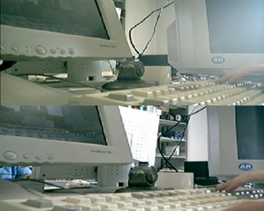 The output required by the shuttles to produce 3D view
3D screens: Sharp 3D LCD Display
Here is another kind of device: 3D displays. This technology is emerging and it seems it will be the future of computers displays (maybe even TV). This type of display allows the user to see 3D without any other device. no glasses, the screen itself handles this part.
In this project, we could test and use a very recent Sharp 3D display. Here below is an explanation about this technology:
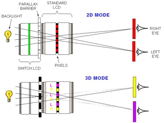 Sharp 3D LCD display and the parallax barrier.
There is a parallax barrier, which has the same role as active glasses: to hide parts of the picture to one eye, and to show some other to the other eye. Actually, the system is a bit more complex: the parallax barrier doesn’t hide pixels, but only pixels components (red, green and blue).
That means that in order to generate the final buffer, we need to interlace pixels (left right left right), but also to shift components.
For instance, here is the original left buffer:
LR0LG0LB0, LR1LG1LB1, LR2LG2LB2, LR3LG3LB3…
And the right buffer:
RR0RG0RB0, RR1RG1RB1, RR2RG2RB2, RR3RG3RB3…
(LR2 is the red component of the 3rd pixel of the left buffer, for instance)
Then the final buffer must be
LR0LG0LB0, RR0LG0RB0, LR1RG0LB1, RR1LG1RB1…
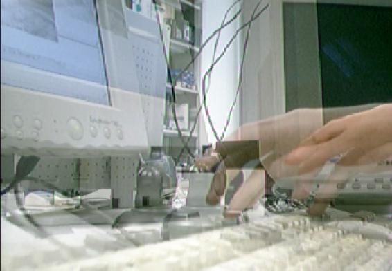 Final buffer for the Sharp Display, without activating the parallax barrier
So the good point of this method is the absence of glasses, and the possibility to make windowed application.
However, the buffer is not so easy to generate, and require per-pixel process, which is a quite heavy task for the processor. Also watching this screen for a while is a bit painful, particularly when we are not used to the screen.
As we could see, the process to generate compatible buffers is completely different from a device to another, and in some case, this process is also extremely costly from a performance point of view.
Performances and high-speed graphics processes
During we were working on the network part, we were thinking about performances. Reading data from the network interface, and recomposing the original stream takes time, and it would be more if we use compression. So the question was easy: how to generate a complex output buffer without slowing down the network/decompression process?
Processing an image at the pixel level is costly. Indeed, we have to deal with video, not images. So here is a simple evaluation: in the case of the Sharp 3D screen, we need to do two main operations for every pixel. The web cams produce 640×480 videos, 30 frames per second. So 640x480x30x2 (2 main operations)=18,432,000 main operations per seconds. Knowing that what we called “main operation” was actually much more than 1 CPU cycle, we really wondered how we could deal with such a task, not slowing the networking and uncompressing process.
Thanks to my experience on 3D processing, I could submit an interesting idea: What about using the hardware capabilities to generate this complex buffer? If we could make a part of the process done by the video card, the main processor would be almost dedicated to network and decompression.
Unfortunately, it was not that easy: to control video card processor cannot be done so easily.
So first we had to create a 3D context, and to display a 3D shape “like” a 2D video.