The Solution : Using the GPU
From 2D videos to 3D scenes
The first step of this conversion was to create a 3D world, and to insert a simple object into.
It was also important to check we could render this object using the programmable pipeline (pixel and vertex shaders).
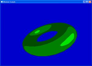 A 3d donut displayed with a cartoon style rendering shader
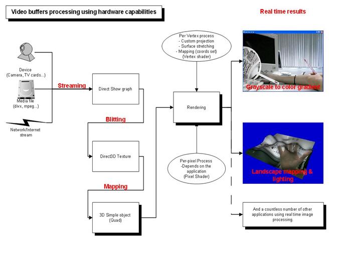
Once we completed this first step, we had to modify the normal rendering filter of DirectShow. Actually, a simple rendering graph contains a video renderer filter, which usually creates the window and display the video data onto this window. Most of applications using DirectShow to render video merely change the position and the style of this window.
To be more precise, when an application uses DirectShow, this application creates its own window, or component, and set the window created by the default renderer as a child of the application’s window. In addition, the border of the DirectShow window is removed, so the video seems to be streamed directly into the application’s window.
A very simple graph to render a webcam
So our task was to remove the renderer, and to replace it with a custom renderer, in order to stream data on a Direct3D texture instead of a normal window.
This custom renderer will fill a Direct3D texture, so no window will be created, but it will allow use to use the video as a map for 3D objects.
The source filter is different, because this graph is generated by the software, while the previous one was created manually. We do not need a decompression filter because the camera filter (directly connected to the driver) can negotiate the media type.
In order to test, we created a landscape, mapped it with our Direct3D texture, generated some bumps, lighted it and displayed it.
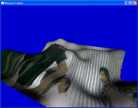
Now that we could go from the 2nd dimension to the 3rd one, we can use the programmable pipeline to perform the generating buffer operations.
The programmable pipeline
There are two ways to consider 3D rendering on recent video cards: using the fixed pipeline, or using the programmable one. The fixed pipeline was the only choice for previous cards generations. The name is “fixed” because all the operation to process and display 3D objects are fixed, and have an hardware implementations. So the projection, rasterization, lighting, polygons filling etc… are accelerated, but there is no way to modify it. For instance, if you want a Phong shading instead of the default Gouraud shading, then you have to write your own software renderer, which will be slow because not accelerated, or to buy a card which can handle programmable pipeline.
On the other hand, the programmable pipeline allows you to define how the graphic card will handle all this process. There are 2 main actors: vertex shaders and pixel shaders.
Both are little part of code, which can be executed by the video card. The vertex shader is called once per vertex, and its purpose is to transform the 3D data into 2D data (projection), and to prepare data to be interpolated for the pixel shader.
The pixel shader is called for every interpolated pixel (calculated from the vertex shader) and is mainly used for colorization.
In the case of our application, the vertex shader will transform the 3D shape to look like a 2D picture, but by doing this we are sure that for every pixel we will have a little process running: the pixel shader.
And since this process works on the video card, it buys a lot of time for the main processor.
A bit closer: HLSL
We needed a language for writing our shaders. There are two main languages: HLSL from Microsoft, and CG from Nvidia. Although both are compatible with DirectX and OpenGL, we preferred to use HLSL, because it’s a bit easier to compile it on the fly by the application. Here below is a simple code, which is actually used to generate a Crystal Eye compatible image (top/bottom):
//vertex shader

struct VS_OUTPUT

{

float4 Position : POSITION;

float2 TexCoord : TEXCOORD0;

float2 TexCoord2 : TEXCOORD1;

};

VS_OUTPUT VS(float4 Position : POSITION, float2 TexCoord : TEXCOORD0)

{

VS_OUTPUT Out;

Out.Position[0]=(2*TexCoord[0])-1;

Out.Position[1]=(2*TexCoord[1])-1;

Out.Position[2]=1;

Out.Position[3]=1;

Out.TexCoord=TexCoord;

Out.TexCoord2=TexCoord;

Out.TexCoord2[0]*=windowsize[0];
return Out;
}
As you can notice, the code of the vertex shader is pretty simple: it sets the z and w components of the vertex position to 1, and adjust x and y depending on the mapping coordinates. This operation will “put” the shape in front of the camera, and stretch it to fill the entire window.
In addition, there are 2 interpolated values: the mapping coordinates (between 0 and 1), and the mapping coordinates multiplied by the window size. This way, for every interpolated pixel, we will get a value between 0 and 1 for the “standard” mapping coordinate (we will use this value to lookup the texture), and a value between 0 and the size of the window. We need this one to know, for instance if the pixel we are processing is odd or even (crucial information in the case of the Sharp screen)
//pixel shader shuttles

float4 PSShuttles( float2 Tex  : TEXCOORD0,float2 preoffs:TEXCOORD1) : COLOR

{

float4 col={0,0,0,0};

Tex[1]*=2;

if(Tex[1]>1)

{

--Tex[1];

col=tex2D(samplerL, Tex);

}

else

{

col=tex2D(samplerR, Tex);

}
return col;
}
The pixel shader code is also quite simple. Because of the vertex shader, we will get the mapping coordinates as a parameter. First, we multiply the y coordinate by 2. If the value is above 1, than mean we are on the lower part of the window. So we reajust the coordinate to have it between 0 and 1, and we perform a texture lookup onto the left image. (Tex2D is the function for texture lookup)
If the coordinate is not above 1, this means we are displaying a pixel of the upper part. After that we just need to lookup onto the right image.
HLSL also allows using techniques, which make the application even easier to modify. Within a technique, you can specify which shader you will use. It is also easy from the main application to get a list of all the available techniques of a compiled file.
For instance:
technique Sharp3D

{

pass P0

{

VertexShader    =     compile vs_2_0 VS();

PixelShader     =     compile ps_2_0 PSSharp3D();

}

}
technique CrystalViewShuttles
{
pass P0
{
VertexShader = compile vs_2_0 VS();
PixelShader = compile ps_2_0 PSShuttles();
}
}
Here above are two of the four techniques we defined in the file. The only difference between techniques is the pixel shader they use (the vertex shader can be the same, because its function is merely to stretch the picture).
And in the main application:
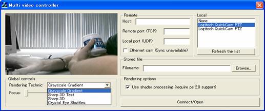 Technique selection in the main application.
Conclusions
This way to process 2D graphics offers many advantages, however some drawbacks are to be expected.
– This model allows performing very fast image operations. Those operations usually cost a lot of processor time, since they are done for every pixels. To sum up, this is a way for real time graphics processing.
– Since the video card handles everything, the main computer has much less stress. Every costly task, like texture lookup, or coordinates interpolation is done by hardware.
– This method puts video or image into Video Memory, which is quite faster than RAM.
– Since the code of vertex and pixel shader is running on the video card, we can access every hardware-coded mathematic function, like matrix operations, or trigonometric functions.
– Usually, when doing stereoscopic image, right and left has to be the same resolution. Since in this case, we deal with mapping coordinates, which are obviously interpolated, we don’t mind this anymore. (However, the stereo results are better with same resolution)
– The color space is not a problem anymore: in usual applications, the programmer has to write a code for every color space. The operations will be different if the color space is RGB32 or R5G6B5…
– Because the code of shader is compiled by the application using it, it can be seen as a module. Therefore it is very easy to make reusable code. For instance, the grayscale to color gradient, the Crystal Eye up-down buffers and the sharp interlaced video are produced by the same application. No need to recompile. Only the shader is different. And since we used HLSL for our shader language, we have only 1 file, containing many techniques.
On the other hand, this model requires a very recent hardware (>=PS 2.0, i.e. GeForce4), and a 3D context needs to be created. In addition, in the case of 3D stereo applications, programmers will need to perform a double pass rendering, once rendering their shape on a texture, and the second render for the image processing.
To sum up, even if there are some black points, this method can be applied very easily, and will allow programmers to cover many different devices without touching their 3D engine, or merely to perform real time image transformations